9.14.2013

3D Print

"MakerBot Replicator" 3D printer is the next step in MiniSumo category:


Strong structured ABS plastics and unordinary design, more design, more solidworks, less makeshift engineerings.

6.27.2013

Convert IF to CASE statements

The results bellow, from IF:
/*IDLE RUN STATE*/  
void idleRunUpdate(){
  //Conditions for transition to a Line Avoid State
  if((sensorSum>=16 && sensorSum<=63)||(sensorSum>=80 && sensorSum<=127)||(sensorSum>=208 && sensorSum<=255)){
    stateMachine.transitionTo(lineAvoidState);
  }
  //Conditions for transition to a Attack State
  if(sensorSum==2||sensorSum==4||sensorSum==6||sensorSum==7||sensorSum==14){
    stateMachine.transitionTo(attackState);
  }
  //Conditions for transition to a Spin State
  if(sensorSum==1||sensorSum==3||sensorSum==8||sensorSum==12){
    stateMachine.transitionTo(spinState); 
  }
  //Conditions for transition to a Overfall Avoid State
  if((sensorSum>=64 && sensorSum<=79)||(sensorSum>=128 && sensorSum<=143)||(sensorSum>=192 && sensorSum<=207)){
    stateMachine.transitionTo(overfallAvoidState);
  }
}

to CASE statements:
/*IDLE RUN STATE*/  
void idleRunUpdate(){
//  Serial.println("idleRunUpdate");
  switch(sensorSum){
    //Conditions for transition to a Line Avoid State
    case 16 ... 63:
    case 80 ... 127:
    case 208 ... 255:
      stateMachine.transitionTo(lineAvoidState);
      break;
    //Conditions for transition to a Attack State
    case 2:
    case 4:
    case 6:
    case 7:
    case 14:
      stateMachine.transitionTo(attackState);
      break;
    //Conditions for transition to a Spin State
    case 1:
    case 3:
    case 8:
    case 12:
      stateMachine.transitionTo(spinState);
      break;
    //Conditions for transition to a Overfall Avoid State
    case 64 ... 79:
    case 128 ... 143:
    case 192 ... 207:
      stateMachine.transitionTo(overfallAvoidState);
      break;
  }
}
The result has saved 12 bytes of memory
3.18.2013

Start Module Implement Yourself

RobotChallange 2013 ordered Start Modules for Robot Sumo, which we can just buy for 15 EUR or implement ourselves.

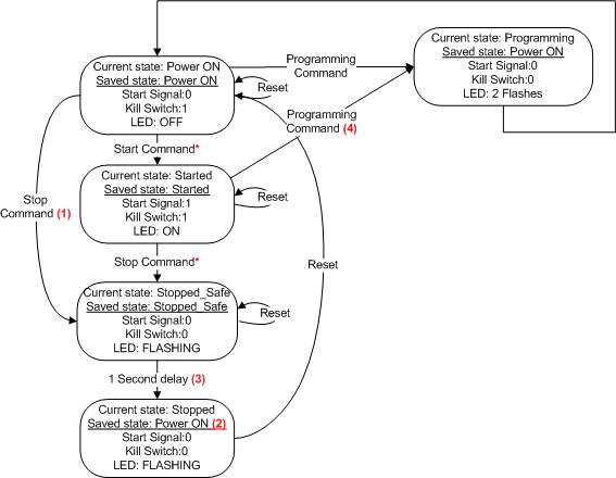
I've implemented that with my own IR Receiver and Arduino IDE, according to Modes Of Operation:


So here is a code example, how to implement it.
UPDATE: 2014.04.04 after RobotChallenge 2014

//IR control PINs
#define RECV ## //Your pin number instead '##'
#define LED ##

//LIMIT COMMAND VALUES
#define MinimumCommandValue 0xC4
#define MaximumCommandValue 0xFE
#define UnderMinimumCommandValue 0x00 ... 0xC3
#define OverMaximumCommandValue 0xFF

//EEPROM ADDRESS
#define StateAddress   0
#define CommandAddress 1

//EEPROM StateValues
#define POWERON 0
#define STARTED 1
#define STOPPED 2
//OVERALL NUMBER OF STATES
#define NumOfStates 2

//THE LIBRARIES YOU NEED
#include <IRLib.h>
#include <EEPROM.h>

//THE STATES YOU NEED TO DECLARE
State powerOnState    = State(powerOnEnter, powerOnUpdate, powerOnExit);
State idleRunState    = State(idleRunUpdate);
State stoppedState    = State(stoppedSafe,stoppedUpdate, NULL);
/*MORE OF YOUR STATES HERE*/

//THE STATE YOU START FROM
FiniteStateMachine stateMachine = FiniteStateMachine(powerOnState);

//VARIABLES
int STOP, STOP2,  START, START2;
byte StateValue, CommandValue;

//INIT IR RECEIVER
IRrecv My_Receiver(RECV);
IRdecode My_Decoder;

void setup(){
/*PUT ALL YOUR SETUPS*/
  pinMode(LED, OUTPUT);
  pinMode(RECV,  INPUT);
//RESTORE THE PROGRAMMED COMMAND VALUE FROM EEPROM
//RESTORE THE STATE VALUE AFTER UNPREDICTED TURN OFF
  RestoreCommandStateValues();
  My_Receiver.enableIRIn();
//RETURN TO THE RESTORED STATE
  ReturnToCurrentState();
}

void loop() {
  check_irrecv_signal();
/*YOUR ESSENTIAL FUNCTIONS*/
  stateMachine.update();

}

void check_irrecv_signal(){
  if (My_Receiver.GetResults(&My_Decoder)) {
    My_Decoder.decode();
//ACCORDING TO THE STATE, CHOOSE COMMANDS
    switch(StateValue){
      case POWERON:
        if(My_Decoder.value == START || My_Decoder.value == START2){
           startCommand();
         }                  
         remoteStopProgramCommands(); break;
      case STARTED: remoteStopProgramCommands(); break;
      case STOPPED: break;
    }
    My_Receiver.resume();      //Prepare to receive the next value 
  }
}

void remoteStopProgramCommands(){
  if(My_Decoder.value == STOP || My_Decoder.value == STOP2) stopCommand(); //Cannot use in switch because STOP is not a constant
  switch(My_Decoder.value){
//THESE ARE POSSIBLE PROGRAMM COMMAND VALUES
    case 0x12C4 ... 0x12FE:
    case 0x1AC4 ... 0x1AFE: programmCommand(); break;
  }
}

void RestoreCommandStateValues(){
  CommandValue = EEPROM.read(CommandAddress);
  switch(CommandValue){
    case UnderMinimumCommandValue:
    case OverMaximumCommandValue:
      CommandValue = MinimumCommandValue;
      EEPROM.write(CommandAddress, CommandValue);
      break;
  }
  makeStartStopValues();
  StateValue = EEPROM.read(StateAddress);
  if(StateValue > NumOfStates){
    StateValue = POWERON;
    EEPROM.write(StateAddress, StateValue);
  }

}

void makeStartStopValues(){
//ACCORDING TO NEW SWEDEN IR REMOTE YOU MAY
//GET 2 DIFFERENT VALUES AT THE SAME BUTTON
//BUT DIFFERENT PUSH TIMES
  STOP = CommandValue + 0x1100;
  STOP2 = CommandValue + 0x1900;
  START = STOP + 1;
  START2 = STOP2 + 1;
}

void ReturnToCurrentState(){
  switch(StateValue){
    case POWERON: break;
    case STARTED: startCommand(); break;
    case STOPPED: stopCommand(); break;
  }
}

void startCommand(){
  StateValue = STARTED;
  EEPROM.write(StateAddress, StateValue);
/*ENABLE DRIVERS HERE*/
  digitalWrite(RXLED, HIGH);
  stateMachine.transitionTo(idleRunState);
}

void stopCommand(){
/*DISABLE DRIVERS HERE*/
  StateValue = STOPPED;
  EEPROM.write(StateAddress, StateValue);
  stateMachine.transitionTo(stoppedState);
}

void programmCommand(){
/*DISABLE DRIVERS HERE*/
  StateValue = POWERON;
  EEPROM.write(StateAddress, StateValue);
  CommandValue = My_Decoder.value & 0x00FE;
  EEPROM.write(CommandAddress, CommandValue);
  makeStartStopValues();
//FLASH THE LED 2 TIMES 500MS
  LED_FLASHING(2, 500);
  stateMachine.transitionTo(powerOnState);
}

/*POWER ON STATE*/ 
void powerOnEnter(){
/*YOUR CODE HERE*/
}
void powerOnUpdate(){
/*YOUR CODE HERE*/
}  
void powerOnExit(){
/*YOUR CODE HERE*/
}

/*IDLE RUN STATE*/  
void idleRunUpdate(){
/*YOUR CODE HERE*/
}

/*STOPPED_SAFE STATE*/
void stoppedSafe(){
  LED_FLASHING(4, 250);
  StateValue = POWERON;
  EEPROM.write(StateAddress, StateValue);
}
/*STOPPED STATE*/
void stoppedUpdate(){
  while(1){
    LED_FLASHING(5, 500);
  }
}

1.31.2013

A-Silicone or PU Tires?

Tested polyurethane rubber with the surface of the dohyo, with 32-07 Monitor/Slip and Friction from Testing Machines Inc.
Introduction:
Slip and Friction testing aids in the evaluation of chemicals and additives used to create or minimize the degree of friction between two contacting test specimens.

Applications:
Paper, Flexible Packaging, Foils, Rubber, Plastics, Wood,
Linoleum, Metal, Printing, Coatings, Composites

Specifications:

  • Selectable speed from 5 to 43 cm/min (2 to 17 inch/min)
  • Selectable travel distance from 2.5 to 30.5 cm (1 to 12 in.)
  • Meets TAPPI T816, T549, and ASTM D1894

Features:

  • Digital display, storage and editing of up to 100 readings, and selectable units (COF or grams)
  • Settable limits
  • Statistics-average, standard deviation, high/low results.
  • Report printout with built in printer
  • RS-232
  • Static and kinetic coefficient of friction calculated in one operation.
  • Direct drive arm with unique skid control.
  • Sled-connecting mechanism ensures level pulling action.
  • Easily interchangeable sleds.
  • Full color easy to read Display

Instrument size:
Depth: 495 mm (19.5 in.)
Height: 508 mm (20 in.)
Width: 515 mm (20.3 in.)
Weight 25 kg (55 lb)
PDF product sheet:
Monitor/Slip and Friction

Product Video:

Brief test results:
* TEST REPORT *
Test Name: SL
Date: 31 Jan 2013

Sample ID: -
Sled Type: B - 200g (.44Lb)
Sled Info: -
Speed: 10cm/min
Travel: 20cm
Unit: COF

Total Meas.: 3
Rejected: 0
Static:
 -> Mean: .654
 -> SD: .089
 -> Lo: .601 (#1)
 -> Hi: .758 (#2)
Kinetic:

 -> Mean: 1.536
 -> SD: .210
 -> Lo: 1.410 (#1)
 -> Hi: 1.780 (#2)

Reading #: S K (X=reject)
 1: .601 1.410
 2: .758 1.780
 3: .604 1.420

* END *

Conclusion:
Graph bellow is found from motor parameters, by ramming the robot to the wall.
  1. As expected, static is lower than kinetic friction coefficient.
  2. These aren't final results, because 3 measurements at one speed means nothing.
  3. It is essential to conduct full experiment at different speeds and normal loads, in order to achieve force vs speed load graph and compare with DC motor load graph.
  4. Next: Full experiment conduction with PU and silicone rubbers.


Useful links:

1.30.2013

Rotor Inertia Measurement

How do we measure rotor inertia?
We can calculate it out of free run.

Method:
  • Connect motor to the battery;
  • Measure no-load current;
  • Connect oscilloscope to the terminals;
  • Disconnect the battery;
  • Let the single measurement appear in the oscilloscope.

Results:
We measured free run BEMF dynamic process, which is equivalent for speed.
We can approximate the achieved graph to linear, which will allow us to use approximated differential dynamics:
  1. Main dynamic formula (M_din - dynamic torque, M_t.v. - no load torque).
  2. Useful torque.
  3. Dynamic Torque equal to No Load Torque.
  4. Torque and current link.
  5. EMF and angular velocity link.
  6. Voltage balance equation.
Moment of inertia is equal to:

Where I_t.v. - no load current, k - motor constant, T - time, E_bat - battery EMF, r_a - armature resistance, r_bat - battery resistance.

Simulation:
Simscape electrical in Matlab, helps us to have this approximated dynamic process and calculate the rotor inertia, which is equal to 1,081e-4 kgm^2:
Conclusion:
This is quite accurate method for rotor inertia calculation, if the gearmotor has static load (friction), which linearised the exponential graph of the speed.

Cast Silicone Tires

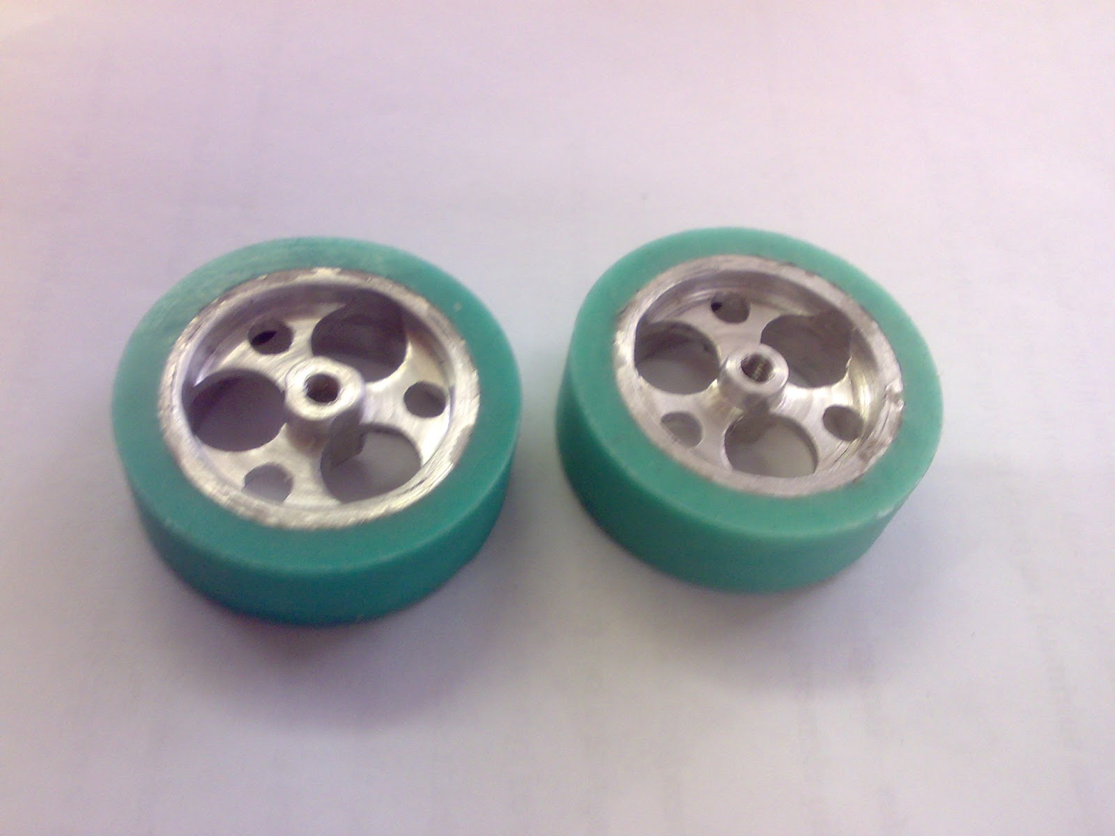
Casted new tires with Elite Double 22 from Zhermack

A-Silicone for laboratory model duplication. Ideal for duplicating models with slight undercuts and casting investments. Use of a plastic duplication flask is recommended. Available in light green for better definition of detail.

Advantages:
  • Mixing facilitated by the 1:1 base to catalyst ratio;
  • High fluidity: does not require mixing in a vacuum;
  • Absolute precision for faithful reproduction of detail;
  • Dimensional stability over time and non-deformability, allowing a number of duplications to be made;
  • Compatible with all plasters, polyurethane resins, phosphate investments and acrylic resins.

Characteristics:
  • Extreme fluidity;
  • Versatile, thanks to the 22 Shore A hardness;
  • Light green colour.

DOWNLOAD:
Center the rims in the form, and apply the mixed liquid to the gap. Polimerisation shouldn't take long, about half an hour. In the result we get newly casted tyres with perfect friction (while new).


1.04.2013

Block Diagram


Electrical energy source ES feeds programable logic controller together with the voltage feedback. Electrical energy flows to both drivers D, which are controlled with PLC and regulate the power for the motors M, where the energy is converted to mechanical. Both motors drive a single transmission device TD, which is actually a full robot mechanical system, except motors, and a Dohyo together, energy parameters are transformed to fit the work unit WU, wich is an opponents robot system and a Dohyo ring too.
The force you need to push the opponent have to be bigger than critical friction force of the opponent's wheels and the Dohyo surface.

Conclusion:
You don't need an enormous power for motors, only slightly bigger than the product of critical friction force of your TD and prefered nominal speed (e. 10cm/s, depends on termal ability, should not overheat).

12.26.2012

SolidWorks Drawings Update

This documentation is required for my cource work. I use SolidWorks Drawings, user friendly environment and fast view creation, drawings made in no time.
The file is in CAD design section. 2012.12.‎31, ‏‎20:43:38

12.15.2012

Acceleration

When I first tried to launch this robot, I've set the full speed to have a good show.
But I've noticed that the front had been raised significantly at full thrust.
If my robots front is raised each attack state, he's dead from the start.

It needs a Soft Start, maximum acceleration allowed to drive the platform.

Recently I've been playing to solve that problem.
Robot has tactile surface sensors - micro switches, which deactivate if the front is raised.

With the help of MegunoLink Tool, Analog reading, Serial communication and code adjustment, we can make an experiment. The Report is bellow.

My course project asks for 20:1 speed regulation range, so speed is 5% steps discrete.
A delay between steps is adjusted.

Adjustment results:
  • Full thrust: No Soft Start applied, as you already noticed that the front has raised, Switch1 readings shows that 0 value, which is OFF. 270ms flying.
  • 1 ms between steps: Not enough yet, 237ms flying.
  • 2ms between steps: 220ms flying blade.
  • 3 ms between steps: 193ms flying blade
  • 4 ms between steps: 159ms max flying blade, unstable yet.
  • 5ms between steps: Eureka the Golden middle! No flying blades.
Conclusion:
It might be better to add a millisecond as 20% more in reserve, because the dead zone for switches is 2mm (~0.1") between flying blade and surface. Rate of voltage change should be 92.5~111 V/s, provides a Soft Start for motors.

Update 2013.01.03: Another more accurate way to find out if the blade is being raised:
  1. Place a sheet of standard A4 paper on the surface of Dohyo in front of the vehicle;
  2. Soft start it to full speed;
  3. Do it several times;
  4. If the blade gets on top of the paper, that means it is still being raised, add a millisecond or two between 5% PWM duty cycle steps.
  5. If the paper is being pushed only, configuration is over and you're good to go.

Battery Resistance Measurement

Decided to check out the current peaks and measure the voltage drop on the battery.
The currents FB_L and FB_R are different, because motors have a little difference resistances.
Update 2013.01.04: Motors have the same resistance, the problem is somwhere in the right motor's power line, might be the R_DS(ON) Resistance of the H-bridge, because one of them was prieviously used. Soldering a fresh MC33887 may solve the problem.

Peak currents are 1,69A and 1,33A
Voltage before load 11,74V
Voltage during load 10,37V
So resistance R=(11,74-10,37)/(1,69+1,33)=0,454 Ohm

May be I'll add negative voltage feedback, to compensate the error during loads someday in future.

Love this feature.

Over Fall Sensor

I have always had a problem with my previous Mini Sumo "Raizo" (Seeker II/IIx inspired) the second place winner at RobotChallange 2010 in Austria.
Every time the slope type opponent pulled it's front my robot had the full throttle, which cause over falling. So I thought about tactile surface sensor and not just on but two.
2 microswitches act as a tactile sensors as you can see bellow in photo, where they have been installed.
Each of them going to sense the side, where opponents blade has got under the platform.
Both of them generate an analog signal, which is measured with one of analog inputs of Arduino and decides which one of them is activated.
The method is called Resistor Ladder or R-2R network (digital to analog conversion, or DAC).
A resistor ladder is an electrical circuit made of repeating units of resistors. Cited: Wikipedia "Resistor Ladder"
A part of schematic sheet
Vout = Vref × VAL / 2N;
N = 2 → 2N = 4;
Vref = 5V;
Vout (00, VAL = 0; 11, VAL = 3);
Minimum single step Vout = 5 × 1 / 22 = 1.25V;
Maximum output
Vout = 5 × 3 / 22 = 3.75V;

The truth table
Vout
S1
S0
10bit value
0
0
0
0
1.25
0
1
256
2.50
1
0
512
3.75
1
1
768

So in order to make it work together with the other sensors in one byte we do this chain of substitutions:
  • Make an array of possible weight in the byte:
const byte microswitch[]={0, 64, 128, 192};
  • Create a function with return values, which are dependent on the measured value:
/*SWITCH DETECT*/
byte Switch(){
  int switchVal=analogRead(SWITCH);
  if(switchVal==0)                   return 3;
  if(switchVal>200 && switchVal<300) return 2;
  if(switchVal>400 && switchVal<600) return 1;
  if(switchVal>700 && switchVal<800) return 0;
}
  • Add the microswitch weigth value, which has been chosen from array.
/*SENSOR DATABYTE*/
void SensorSum(){
  sensorSum = sharp_sl[digitalRead(SHARP_SL)]
            + sharp_fl[digitalRead(SHARP_FL)]
            + sharp_fr[digitalRead(SHARP_FR)]
            + sharp_sr[digitalRead(SHARP_SR)]
            + vishay_l[digitalRead( TCRT_L )]
            + vishay_r[digitalRead( TCRT_R )]
            + microswitch[Switch()];
}
Electromagnetic Interference Reduction

In the previous message, you've seen that measured current wasn't so smooth because of the comutation noise in the motor.
There are several ways of filtering the noises from the motors starting from simple to Hi End one:

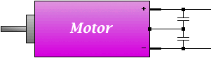
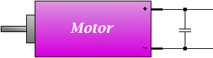
A single-capacitor filter.
The capacitor is simply soldered across the motor terminals.
A two-capacitor filter.
Each capacitor has one lead attached to a motor terminal, and the other lead attached to the case.
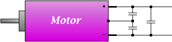
A three-capacitor filter.
This is basically a combination of the one- and two-capacitor circuits.
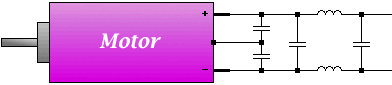
A capacitor-choke filter.
These are usually assembled on a separate circuit board which is then soldered to the motor terminals.
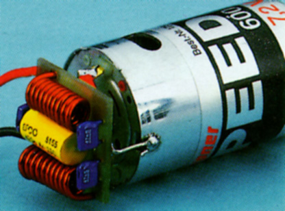
A capacitor-choke filter sold by Graupner, designed to be soldered directly to any 05-sized can motor, such as a Graupner Speed 600. Graupner also sells a Speed 400 sized filter.

Not much of place soldering that stuff to my robot:
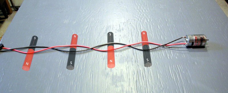
I personally suggest to twist it with a steel wire, to make it more effective.
Twisting the wires making up a circuit results in many smaller magnets with opposing polarity, which cancel each other out.

Citation: www.stefanv.com
Motor Isolation.
A simple isolated power supply for robot motors and circuits

A pseudo-isolated power supply for robot motors and circuits

Armature Current Measurement

With the help of MegunoLink 1.0.6 application form Blue Leaf Software You can measure all sorts of dynamic processes, such as armature current of the motor using arduino analog input and serial communication.
Use just two lines for two motor current feedback:
  Serial.println("{FB_L,T," + String(analogRead(FB_L))+'}');
  Serial.println("{FB_R,T," + String(analogRead(FB_R))+'}');

12.14.2012

Arduino Source Code Update


Split the code into tabs to have an easier access:

  1. Destroyer_3000.ino for global functions and variables;
  2. FSM.ino for Finite State Machine functions;
  3. Loop.ino for critical actions and functions;
  4. Motor.ino for motor speed control;
  5. PWM.ino just for prescaler choice;
  6. Serial_Monitor.ino for sensor data monitoring;
  7. Setup.ino for all the data setup and single run functions;
  8. definitions.h for all global constants.
//http://www.arduino.cc/playground/uploads/Code/FSM_1-6.zip
#include <FiniteStateMachine.h>
Added some more states:
State idleRunState = State(idleRunEnter, idleRunUpdate, NULL); State spinState = State(spinEnter, spinUpdate, spinExit); State lineAvoidState = State(lineAvoidEnter, lineAvoidUpdate, NULL); State attackState = State(attackEnter, attackUpdate, NULL); State overfallAvoidState = State(overfallAvoidEnter, overfallAvoidUpdate, NULL); FiniteStateMachine stateMachine = FiniteStateMachine(idleRunState);
The data sum of 8 sensors might have the result from 0~255 as a byte, so it is not efficient to write a switch-case for that. In order to find all combinations, use windows calc.exe in programmer mode for 1 byte in decimal units. Click "+", "1" and keep clicking "=" to increment the value, check the binary code while clicking.


"B00010001" states that proximity sensor on the left side and left line sensor are active at the same time, but priority is to avoid the line of the Dohyo, so the number "17" will be included in the interval which activates the "lineAvoidState".

During finite state, just toggle constant forward speed for patrolling.
/*IDLE RUN STATE*/ void idleRunEnter(){   motor(50, 50); }
Update it with continuous sensor readings, several if's will do the transitions.
(Update 2012.12.14 17:57): Fixed the condition for attackState, was the same as spinState's, in result robot runs stright forward as forever in idleEnter function, no line detection.
void idleRunUpdate(){   SensorSum();   if(sensorSum==1||sensorSum==3||sensorSum==8||sensorSum==12){     stateMachine.transitionTo(spinState);   }   if((sensorSum>=16 && sensorSum<=63)||(sensorSum>=208 && sensorSum<=255)){     stateMachine.transitionTo(lineAvoidState);   }   if(sensorSum==2||sensorSum==4||sensorSum==6||sensorSum==7||sensorSum==14){     stateMachine.transitionTo(attackState);   }   if((sensorSum>=64 && sensorSum<=79)||(sensorSum>=128 && sensorSum<=143)||(sensorSum>=192 && sensorSum<=207)){     stateMachine.transitionTo(overfallAvoidState);   } }
Under line avoid state are some setups on the enter: a timer, mask, a switch. 2 line sensors are used, so there is 3 combinations of them: left, right and both. Each result drives the system accordingly.
/*LINE AVOID STATE*/void lineAvoidEnter(){   timeOld=millis();   sensorMask=!(sensorSum & 48);   switch(sensorSum & 48){     case 16: timer=600; motor( 0, -50); break;     case 32: timer=600; motor(-50, 0); break;     case 48: timer=1000; motor(-50, -50); break;   } }
While avoiding the line, scan the sensor readings for a change and ignore the previous sensor, while in state in order not to tristate the state. The state will transit back if timer is out or there is a positive sensor result. But there is a condition for both activated line sensors, it will transit to spin state if no sensor was found after timeout.
void lineAvoidUpdate(){   SensorSum();   if(sensorSum & sensorMask > 0 || millis()-timeOld >=timer*8){     if(sensorMask==!48 && millis()-timeOld>=timer*8){       timeOld=millis();       stateMachine.immediateTransitionTo(spinState);     }     stateMachine.immediateTransitionTo(idleRunState);   } }
Analogical situation in the spin state.
/*SPIN STATE*/void spinEnter(){   timeOld=millis();   sensorMask=!(sensorSum & 9);   switch(sensorSum & 9){     case 0: timer=1000; motor(-50, +50); break;     case 1: timer=1000; motor(-50, +50); break;     case 8: timer=1000; motor(+50, -50); break;   } } void spinUpdate(){   SensorSum();   if(sensorSum & sensorMask > 0 || millis()-timeOld >=timer*8){     stateMachine.immediateTransitionTo(idleRunState);   } } void spinExit(){ }
Functions not programmed yet.
void attackEnter(){ } void attackUpdate(){ } void attackExit(){ } void overfallAvoidEnter(){ } void overfallAvoidUpdate(){ } void overfallAvoidExit(){ }

12.12.2012

Specifications

I present my mini sumo robot "Destroyer 3000"

Parts:
Aluminum body;
2 aluminum wheels with casted PU tires;
3 cell LiPo 0.8Ah battery

Mechanical:
2x 12V 1000RPM motors;
2x Pairs of 1:2 Bevel gears;

Electronics:
1x Arduino Nano v3.0;
2x Freescale MC33877 drivers;

Sensors:
1x TSOP31236 IR receiver;
4x SHARP 340K 40cm proximity sensors;
2x TCRT1000 Line sensors;
2x Overfall detection microswitchs;


A photo render of 3D CAD design

The design files are in CAD design section