RobotChallange 2013 ordered Start Modules for Robot Sumo, which we can just buy for 15 EUR or implement ourselves.
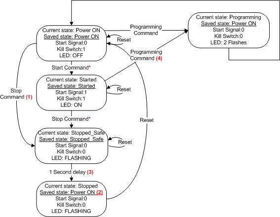
I've implemented that with my own IR Receiver and Arduino IDE, according to Modes Of Operation:

So here is a code example, how to implement it.
UPDATE: 2014.04.04 after RobotChallenge 2014
//LIMIT COMMAND VALUES
void loop() {
void startCommand(){
I've implemented that with my own IR Receiver and Arduino IDE, according to Modes Of Operation:
So here is a code example, how to implement it.
UPDATE: 2014.04.04 after RobotChallenge 2014
//IR control PINs
#define RECV ## //Your pin number instead '##'
#define LED ##
//LIMIT COMMAND VALUES
#define MinimumCommandValue 0xC4
#define MaximumCommandValue 0xFE
#define UnderMinimumCommandValue 0x00 ... 0xC3
#define OverMaximumCommandValue 0xFF
//EEPROM ADDRESS
#define StateAddress 0
#define CommandAddress 1
//EEPROM StateValues
#define POWERON 0
#define STARTED 1
#define STOPPED 2
//OVERALL NUMBER OF STATES
#define NumOfStates 2
//THE LIBRARIES YOU NEED
#include <IRLib.h>
#include <EEPROM.h>
#include <FiniteStateMachine.h>
//THE STATES YOU NEED TO DECLARE
State powerOnState = State(powerOnEnter, powerOnUpdate, powerOnExit);
State idleRunState = State(idleRunUpdate);
State stoppedState = State(stoppedSafe,stoppedUpdate, NULL);
/*MORE OF YOUR STATES HERE*/
//THE STATE YOU START FROM
FiniteStateMachine stateMachine = FiniteStateMachine(powerOnState);
//VARIABLES
int STOP, STOP2, START, START2;
byte StateValue, CommandValue;
//INIT IR RECEIVER
IRrecv My_Receiver(RECV);
IRdecode My_Decoder;
void setup(){
/*PUT ALL YOUR SETUPS*/
pinMode(LED, OUTPUT);
pinMode(RECV, INPUT);
//RESTORE THE PROGRAMMED COMMAND VALUE FROM EEPROM
//RESTORE THE STATE VALUE AFTER UNPREDICTED TURN OFF
RestoreCommandStateValues();
My_Receiver.enableIRIn();
//RETURN TO THE RESTORED STATE
ReturnToCurrentState();
}
void loop() {
check_irrecv_signal();
/*YOUR ESSENTIAL FUNCTIONS*/
stateMachine.update();
}
void check_irrecv_signal(){
if (My_Receiver.GetResults(&My_Decoder)) {
My_Decoder.decode();
//ACCORDING TO THE STATE, CHOOSE COMMANDS
switch(StateValue){
case POWERON:
if(My_Decoder.value == START || My_Decoder.value == START2){
startCommand();
}
remoteStopProgramCommands(); break;
case STARTED: remoteStopProgramCommands(); break;
case STOPPED: break;
}
My_Receiver.resume(); //Prepare to receive the next value
}
}
void remoteStopProgramCommands(){
if(My_Decoder.value == STOP || My_Decoder.value == STOP2) stopCommand(); //Cannot use in switch because STOP is not a constant
switch(My_Decoder.value){
//THESE ARE POSSIBLE PROGRAMM COMMAND VALUES
case 0x12C4 ... 0x12FE:
case 0x1AC4 ... 0x1AFE: programmCommand(); break;
}
}
void RestoreCommandStateValues(){
CommandValue = EEPROM.read(CommandAddress);
switch(CommandValue){
case UnderMinimumCommandValue:
case OverMaximumCommandValue:
CommandValue = MinimumCommandValue;
EEPROM.write(CommandAddress, CommandValue);
break;
}
makeStartStopValues();
StateValue = EEPROM.read(StateAddress);
if(StateValue > NumOfStates){
StateValue = POWERON;
EEPROM.write(StateAddress, StateValue);
}
}
void makeStartStopValues(){
//ACCORDING TO NEW SWEDEN IR REMOTE YOU MAY
//GET 2 DIFFERENT VALUES AT THE SAME BUTTON
//BUT DIFFERENT PUSH TIMES
STOP = CommandValue + 0x1100;
STOP2 = CommandValue + 0x1900;
START = STOP + 1;
START2 = STOP2 + 1;
}
void ReturnToCurrentState(){
switch(StateValue){
case POWERON: break;
case STARTED: startCommand(); break;
case STOPPED: stopCommand(); break;
}
}
void startCommand(){
StateValue = STARTED;
EEPROM.write(StateAddress, StateValue);
/*ENABLE DRIVERS HERE*/
digitalWrite(RXLED, HIGH);
stateMachine.transitionTo(idleRunState);
}
void stopCommand(){
/*DISABLE DRIVERS HERE*/
StateValue = STOPPED;
EEPROM.write(StateAddress, StateValue);
stateMachine.transitionTo(stoppedState);
}
void programmCommand(){
/*DISABLE DRIVERS HERE*/
StateValue = POWERON;
EEPROM.write(StateAddress, StateValue);
CommandValue = My_Decoder.value & 0x00FE;
EEPROM.write(CommandAddress, CommandValue);
makeStartStopValues();
//FLASH THE LED 2 TIMES 500MS
LED_FLASHING(2, 500);
stateMachine.transitionTo(powerOnState);
}
/*POWER ON STATE*/
void powerOnEnter(){
/*YOUR CODE HERE*/
}
void powerOnUpdate(){
/*YOUR CODE HERE*/
}
void powerOnExit(){
/*YOUR CODE HERE*/
}
/*IDLE RUN STATE*/
void idleRunUpdate(){
/*YOUR CODE HERE*/
}
/*STOPPED_SAFE STATE*/
void stoppedSafe(){
LED_FLASHING(4, 250);
StateValue = POWERON;
EEPROM.write(StateAddress, StateValue);
}
/*STOPPED STATE*/
void stoppedUpdate(){
while(1){
LED_FLASHING(5, 500);
}
}
hola me puedes ayudar en que parte del codigo coloco mi progrmacion y cambio el numero de dato que envio
ReplyDeleteHow am I supposed to help you?
ReplyDeleteHi,
ReplyDeleteYesterday I tested your program with "Arduino Uno"
All works !!!!
But it's necessary change the original code:
State powerOnState = State(powerOnEnter, powerOnUpdate, powerOnExit);
State idleRunState = State(idleRunUpdate);
State stoppedState = State(stoppedSafe,stoppedUpdate, NULL);
with correct code (including &):
State powerOnState= State(&powerOnEnter, &powerOnUpdate, &powerOnExit);
State idleRunState= State(&idleRunUpdate);
State stoppedState= State(&stoppedSafe,&stoppedUpdate, NULL);
After programming led flashing 3 time !!
Good Job
Thanks
hello I have problems to record the hex to the control you can help me to record it
DeleteIs it reference / interface / include operator, I am not best at c programming.
DeleteHi,
ReplyDeleteThe last time i used this instructions:
====================== Programming the device
For those who want to build their own modules based on this code and microcontroller, it is important that the fuse are correct when uploading the hex-file. Incorrect settings may brick your chip.
Using the following avrdude command is used when programming the prebuilt modules. It utilizes the AvrISP MKII programmer, so if you use any other programmer, change the programming command accordingly. Make sure to be in the correct folder, or replace "StartModule.hex" to the correct path to your hex-file.
avrdude -pt13 -cavrispmkII -Pusb -u -Uflash:w:StartModule.hex:a -Ulfuse:w:0x79:m-Uhfuse:w:0xef:m
These fuse bits sets the following. The ones marked (important) have the potential to brick your system if set incorrectly. Set them as below and you should be fine:
No brownout detection
No clock division by 8
No Debug wire
No Eeprom preserve through programming
No reset disable (important)
Self Programming enabled (important)
SPI programming enabled (important)
Clock source as 4.8MHz, 14CK 64ms startup time (important)
No watchdog
You can check http://www.engbedded.com/fusecalc for further information about fusebtis.
When the flash has been written, the module will go into "Stopped" state, which means it will blink slowly. Cycle the power and it should be ready to use.